Linked List Reversal
Problem Description
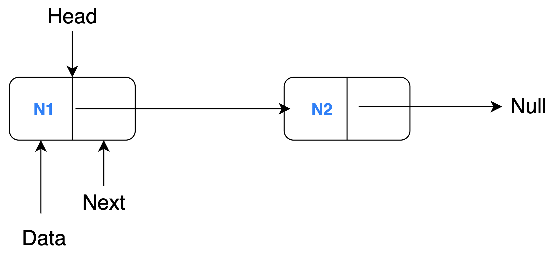
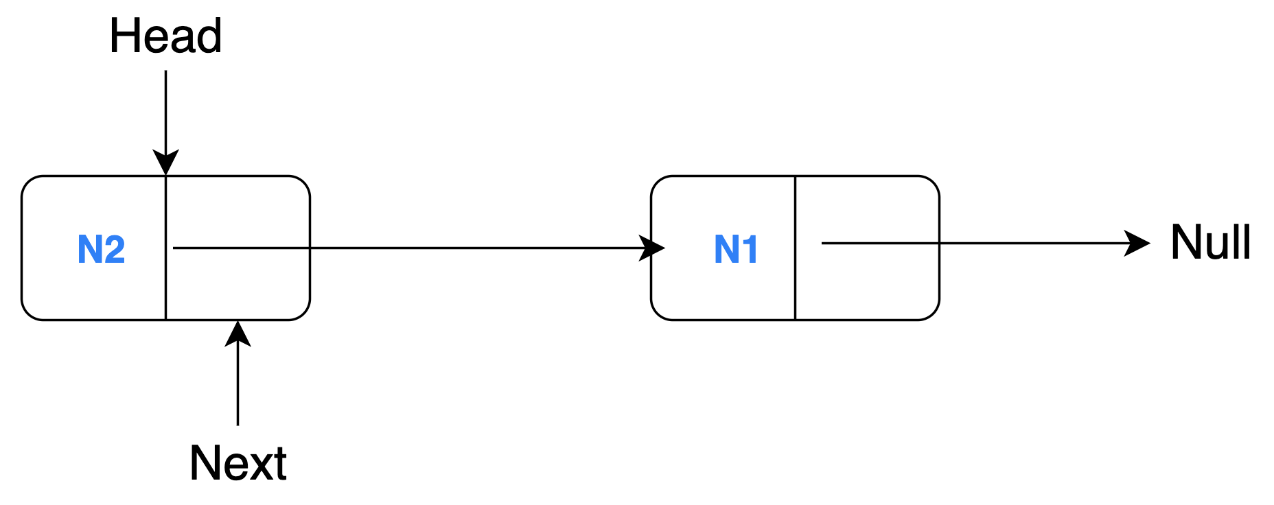
Let's see a simple example where a linked list with 2 nodes (N1 and N2) is reversed through model transformation.
A linked list is a collection of sequentially connected nodes where each node contains some data and a reference (pointer) to the next node. The head of a linked list is the first node of the list i.e. the node that is not being referenced. The node at the end (tail) cannot point to the next node hence it references to null. A regular linked list comprises of these characteristics, so, we need to just change them appropriately to reverse the order of the nodes.
Source Model

Target Model

You will need to understand this example's project structure before you read any line of code:
graph BT
    B[Source Model] -->|conforms to| A[Linked List Metamodel];
    C[MT Execution Engine] -->|reads| B;
    C -->|writes| D[Target Model];
    C -->|executes| E[MT Definition];
    E -->|uses| A;
D -->|conforms to| A;This example slightly differs from general model transformation projects because the source and target metamodels are the same (as seen in the figure above). The model transformation definition (MT Definition) must adhere to the MTL syntax and semantics, so it has been documented separately for each MTL provided in the MTL Solutions section at the bottom of this page. Next, we will look at other important files required for the model transformation.
Metamodel
The source and target model must conform to the linked list metamodel. This contains the necessary information regarding the structure of the linked list at an abstract level such that certain characteristics of the linked list can still be changed in the model files. Look at the pseudocode below for the linked list metamodel:
CLASS Linked List
        SET reference to a Node object as HEAD
        INIT LIST of Node objects

CLASS Node
        INIT string DATA attribute
        SET reference to the NEXT Node object in the linked list
The metamodel contains two class definitions for Linked List and Node objects. The Linked List class has a HEAD attribute (as a reference) and a LIST of Node objects are initialised. The Node object contains a DATA field of the 'String' data type and a pointer (reference) to the NEXT object of the same type (Node) in the list.
Source Model
A sample source model (generally in XMI format) would look like the snippet below:
<LinkedList head="N1">
    <node name="N1" next="N2"/>
    <node name="N2"/>
</LinkedList>
Target Model
A sample target model (also generally in XMI format) which is generated by performing a rule-based transformation on the source model would look like this:
<LinkedList head="N2">
    <node name="N1"/>
    <node name="N2" next="N1"/>
</LinkedList>